Address
Malik Saleem Plaza, New City, Wah
Pakistan
WhatsApp: +92 327 5100047
Email: info@developmech.com
Work Hours
Monday to Friday: 3PM - 11AM
Weekend: 10AM - 5PM
Address
Malik Saleem Plaza, New City, Wah
Pakistan
WhatsApp: +92 327 5100047
Email: info@developmech.com
Work Hours
Monday to Friday: 3PM - 11AM
Weekend: 10AM - 5PM

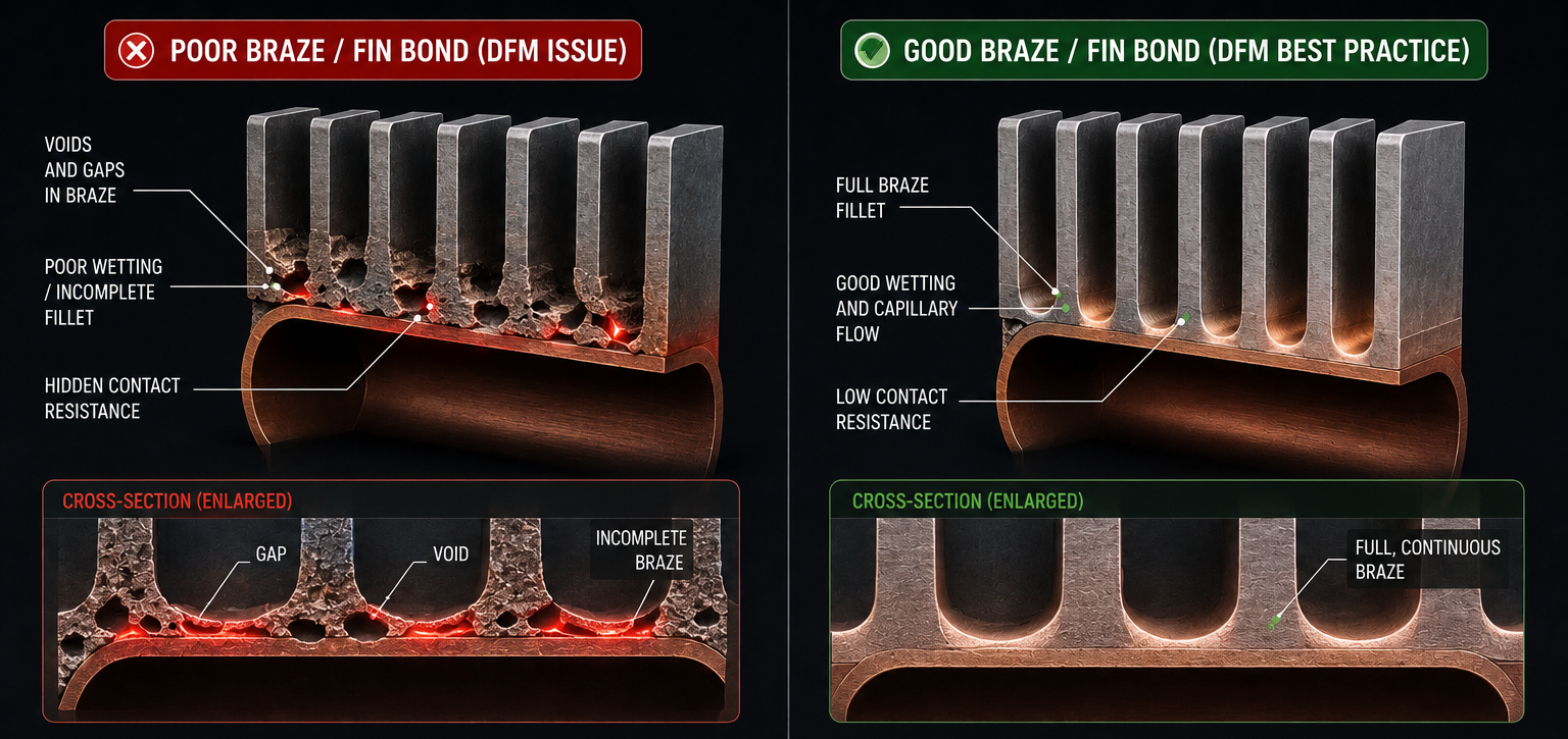
Why a heat exchanger that passes on the spec sheet still overheats, over-pumps, or leaks in the real world and how to catch it before you build
Developmech | Thermal Analysis & CFD
On paper, a heat exchanger is a solved problem. Pick an area, plug in the flow rates and temperatures, run the ε-NTU or LMTD math, and the spreadsheet tells you it will reject the heat you need. Then you build it, drop it into the actual product, and it runs hot.
This is one of the most common and most expensive surprises in hardware. A heat exchanger a cold plate, a plate pack, a compact liquid-cooling loop, a radiator is where clean textbook math meets messy real fluid behavior, and the gap between the two is where products throttle, pumps scream, joints leak, and launch dates slip.
Here are the six mistakes that most often separate a heat exchanger that works on the spec sheet from one that works in the field and what each one costs.
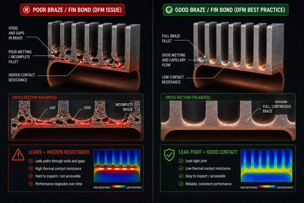
A poor braze with hidden contact resistance and leak risk (left) vs an accessible, inspectable, leak-tight joint (right).
A heat exchanger lives or dies at its joints. Brazes, fin bonds, and welds control both leak-tightness and thermal contact and they’re exactly where DFM gets ignored. Poor braze access, unrealistic tolerances in thin channels, burrs that block microchannels, or a fin-to-plate bond with hidden contact resistance turn a good thermal design into a leaking, underperforming one.
The cost. Leaks, scrap, low yield, and a thermal contact resistance that quietly eats the performance you paid for in the core design.
The fix. Design the joints and the manufacturing process alongside the thermal core. Make brazes and welds accessible and inspectable, tolerance the channels to what the process can hold, and account for contact resistance and bond quality in the thermal model not as an afterthought.
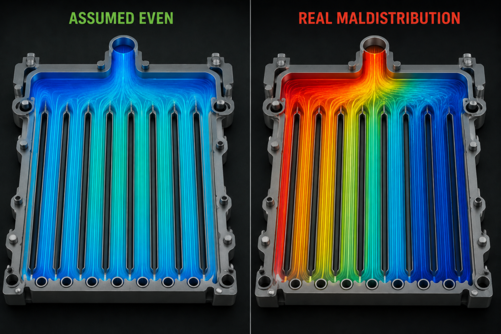
Uniform flow is assumed (left); real header geometry starves some channels and floods others (right).
The sizing math assumes every tube, channel, or plate sees the same flow. Real headers and manifolds don’t cooperate. Flow takes the path of least resistance, some channels get starved, and the “average” performance your spreadsheet promised never shows up you get hot channels, cold channels, and a device that underperforms its rating.
The cost. An exchanger that tests 20–40% below its predicted capacity discovered after tooling forcing a header redesign or a larger unit.
The fix. Treat flow distribution as a design variable, not an assumption. CFD of the header and core exposes maldistribution early, and inlet placement, header geometry, and distributor features can be tuned before anything is built.
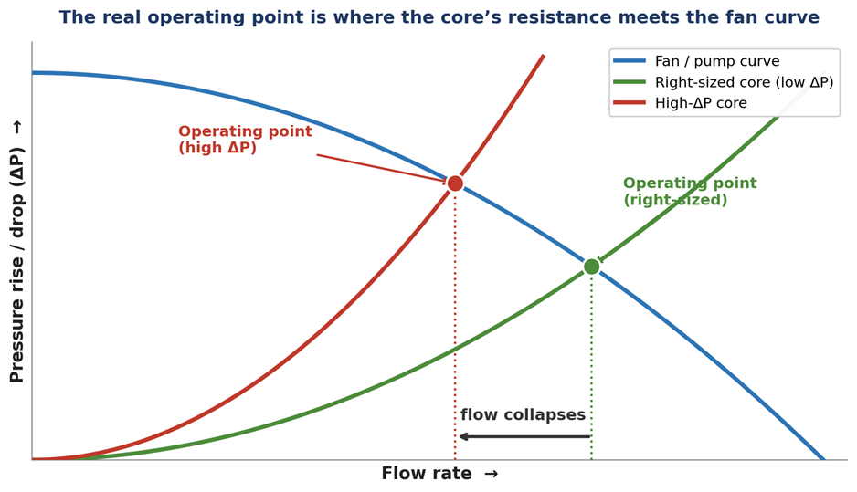
The real operating point is where the exchanger’s resistance curve meets the actual fan/pump curve a higher-ΔP core drops the flow, and the cooling with it.
Every feature that boosts heat transfer tighter fins, smaller channels, turbulators also raises pressure drop. Design for thermal performance alone and you get a beautiful exchanger that your actual pump or fan can’t push flow through. On the fan or pump curve, the operating point shifts, flow collapses, and thermal performance goes with it.
The cost. An oversized, louder, power-hungry pump or fan bolted on to rescue the design or a device that never reaches its rated flow at all.
The fix. Design against the thermal-hydraulic trade-off from the start. Size the core and the mover together, overlay the exchanger’s resistance curve on the real fan/pump curve, and find the operating point not just the thermal number.
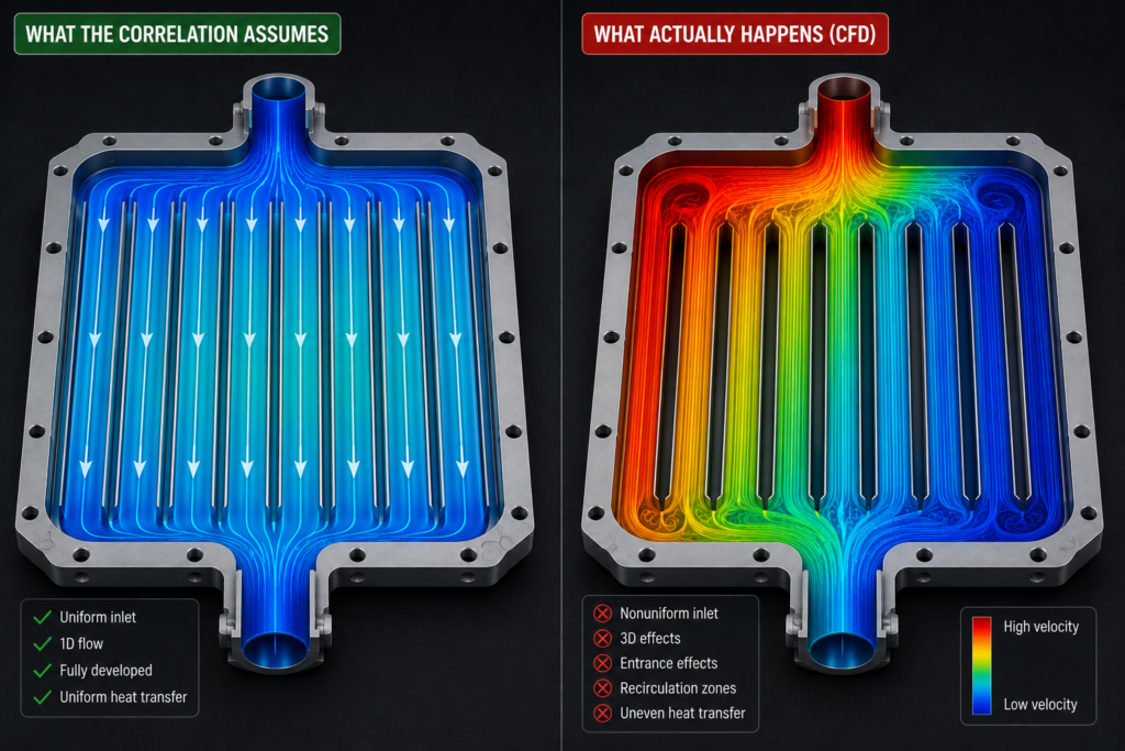
Idealized correlation flow (left) vs the headers, bends, and entrance effects that CFD reveals in the real geometry (right).
ε-NTU, LMTD, and handbook Nusselt correlations assume clean, fully-developed, uniform flow in idealized geometry. A real compact, plate, or microchannel exchanger has headers, bends, entrance regions, and manufacturing variation those correlations never saw. The result is a number that can be confidently, invisibly wrong.
The cost. A design signed off on a correlation that doesn’t apply, with the error surfacing only in the first physical prototype.
The fix. Use correlations for the first-pass sizing, then validate the real geometry with CFD (conjugate heat transfer) before committing. The correlation tells you roughly how big; the simulation tells you whether this specific design actually works.
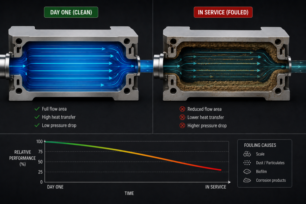
Clean, day-one performance (left) vs fouled channels and steadily degraded performance in service (right).
A heat exchanger tested on the bench brand new and spotless is at the best it will ever be. In service, fouling (scale, dust, biofilm, oil film) builds up and steadily strangles performance. Design to clean performance with no margin and the unit meets spec on day one and misses it by month six.
The cost. Field underperformance, warranty claims, and unplanned cleaning or replacement plus a reputation problem when the product degrades in front of the customer.
The fix. Include a fouling allowance appropriate to the fluid and environment, choose geometries that resist and tolerate fouling, and design for cleanability where the duty demands it. Plan for the dirty exchanger, not the clean one.
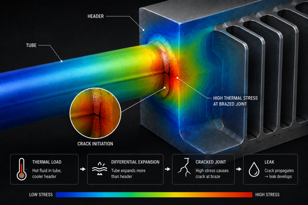
Differential thermal expansion drives stress and, under cycling, cracks at brazed or welded joints.
Heat exchangers run hot, and different parts run at different temperatures. Tubes grow relative to the shell; plates and headers expand against their joints. Under steady operation that’s a stress problem; under thermal cycling every startup, shutdown, and load swing it’s a fatigue problem, and it usually shows up as a cracked braze or a weeping joint.
The cost. Leaks. In a liquid loop near electronics or a battery, a leak isn’t a performance issue it’s a failure and a safety event.
The fix. Run a thermal-structural analysis on the hot geometry, not just a thermal one. Check differential expansion, joint and braze stresses, and thermal-cycling fatigue at the details that actually crack and add flexibility (expansion features, joint design) where the analysis says it’s needed.
Notice the pattern: none of these show up in the sizing spreadsheet. A heat exchanger’s rated capacity is the easy part; whether it delivers that capacity in a real product with a real pump, real fouling, real thermal cycling, and real joints is the engineering that separates a component that works from one that only looked like it would. The spec sheet is where heat exchangers pass. The field is where they’re judged.
At Developmech, we analyze and design heat exchangers and cooling systems the way they actually behave flow distribution and pressure drop by CFD, thermal-structural stress by FEA, and joints designed to be built. If you’ve got a thermal design that has to perform in the real world, not just on paper, we’re glad to take a look.
