Address
Malik Saleem Plaza, New City, Wah
Pakistan
WhatsApp: +92 327 510047
Email: info@developmech.com
Work Hours
Monday to Friday: 3PM - 11AM
Weekend: 10AM - 5PM
Address
Malik Saleem Plaza, New City, Wah
Pakistan
WhatsApp: +92 327 510047
Email: info@developmech.com
Work Hours
Monday to Friday: 3PM - 11AM
Weekend: 10AM - 5PM

High head hydro runners fail by fatigue, erosion, and transients, and none of it shows up on the efficiency curve
Developmech | Structural, Fatigue & Flow Analysis
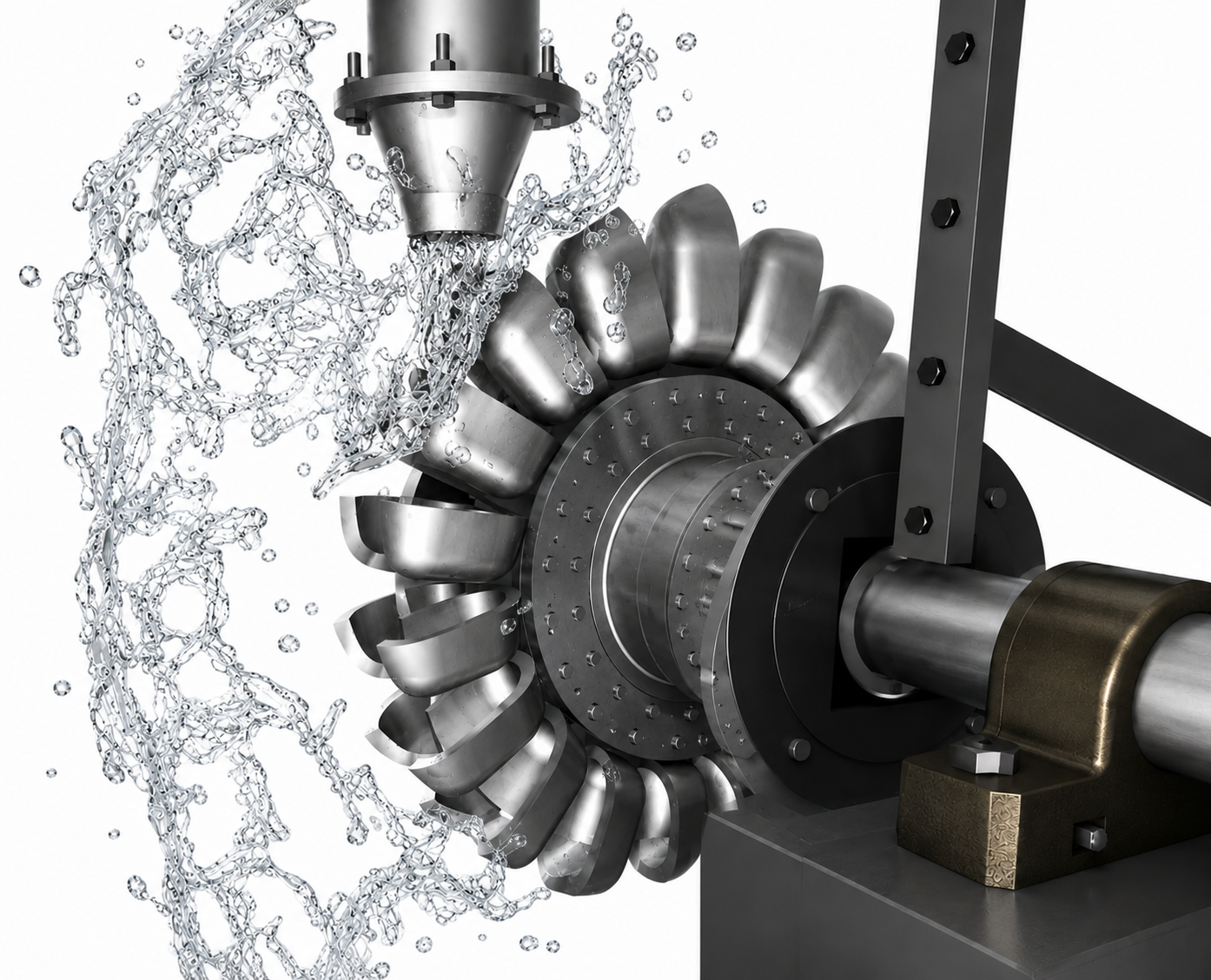
A Pelton wheel is the easiest turbine to explain and one of the easiest to get wrong. A jet hits a bucket, the bucket turns the wheel, and the textbook stops there with a velocity triangle and an efficiency near 90 percent. Nothing in that explanation tells you why runners crack at the bucket root, why efficiency falls away inside one monsoon, or why closing a needle valve too quickly can burst a penstock a kilometer up the hill.
The hydraulics are the easy part. The hard part is that a Pelton runner is a fatigue component, an erosion component, and a rotating structure that has to survive runaway speed, all at once. It is loaded and unloaded once per revolution for its entire life, cut by whatever sand the river carries at over 100 meters per second, and bolted to the bottom of a long steel pipe full of water with no interest in stopping quickly.
Here are the six structural, erosion, and transient reasons Pelton units fail, and what each one costs.
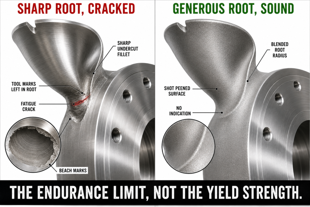
Each bucket is loaded once per revolution. At 500 rpm that is about 260 million cycles a year, so the number that governs is the endurance limit, not the yield strength.
Every bucket is loaded and unloaded once per revolution. At 500 rpm running continuously that is roughly 260 million cycles a year, and more than a billion in four. Nothing designed for finite life survives it. As the jet sweeps the splitter it applies a bending moment that concentrates in the root fillet and at the base of the splitter, exactly where casting porosity, machining marks, and weld repairs like to sit. A runner that looks comfortable against yield can still crack, because at a hundred million cycles the governing number is the endurance limit with the real surface finish and mean stress, not the tensile strength on the material certificate.
The cost. A crack that grows quietly at the bucket root until a bucket liberates, unbalancing a heavy wheel at speed. It usually takes the rest of the runner, the bearings, and several months of generation with it.
The fix. Design for infinite life. Model the jet sweeping the bucket as a transient load, pull the real stress history at the root and splitter, apply the fatigue reductions for surface finish, size, and mean stress, and keep the alternating stress under the endurance limit with margin. Prefer a single piece forged and machined runner over bolted or cast buckets, shot peen the root radius, and set inspection intervals from crack growth analysis rather than the calendar.
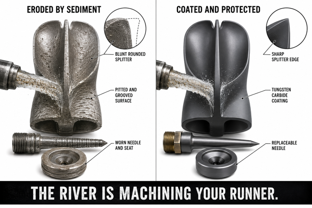
Erosion climbs steeply with jet velocity, so a high head site carrying sediment is a wear problem before it is a hydraulic one.
At 400 meters of head the jet leaves the nozzle at roughly 85 meters per second, and at 1000 meters it is over 130. Every grain of quartz arrives at the same speed, and quartz is harder than the stainless steel the runner is made from. Erosion rate climbs close to the cube of velocity and scales with sediment concentration and particle size. The splitter edge goes first and turns blunt, so the jet stops dividing cleanly, and the bucket surface roughens and loses the shape the hydraulic design depended on. The needle and seat erode in parallel, which spoils the jet and accelerates everything else.
The cost. Several points of efficiency inside a single silt season, annual runner refurbishment that was never in the operating budget, and a machine that never returns to its commissioning performance.
The fix. Treat sediment as a design input, not a site condition. Size desilting basins against the measured particle size distribution rather than a nominal figure, run CFD with particle tracking to find where erosion actually lands, specify hard coatings such as tungsten carbide applied by HVOF, and design the needle and seat as replaceable wear parts.
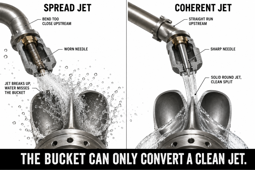
The bucket can only convert a clean, round, coherent jet. Distributor bends and a worn needle spread it, and the losses get blamed on the runner.
A Pelton bucket is designed around a coherent, round jet arriving on a known line at a known velocity, so anything that spoils the jet spoils the machine. A bend too close to the nozzle, a manifold that does not feed every branch evenly, or a worn needle and seat will all make the jet spread. A spread jet delivers part of its momentum outside the bucket, splashes, and interferes with water leaving the bucket ahead of it. On machines with several jets the problem compounds, because discharge from one bucket can cross the path of the next.
The cost. Efficiency losses of a few percent that are usually blamed on runner wear, uneven bucket loading that feeds straight back into the fatigue problem, and vibration.
The fix. Analyze the distributor and nozzle together with CFD, not the nozzle in isolation. Give each nozzle enough straight length upstream, balance the manifold branches, check jet coherence and roundness at the bucket plane, and verify jet geometry against bucket pitch so discharge clears before the next jet arrives.
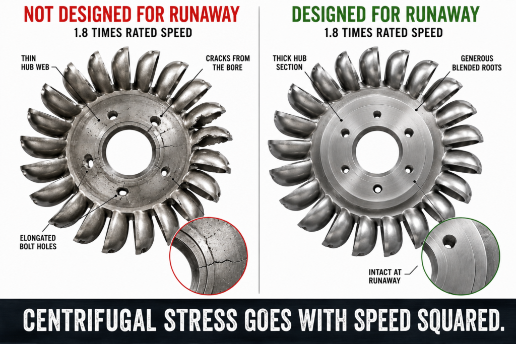
On a full load rejection the unit accelerates to around 1.8 times rated speed. Centrifugal stress goes with speed squared, so it more than triples.
If the generator breaker opens at full load, the turbine loses its braking torque and accelerates until windage and friction balance the jet. For a Pelton machine that runaway speed is typically about 1.8 times rated. Centrifugal stress scales with the square of speed, so the runner sees a little over three times its normal centrifugal load, and the shaft, bearings, and generator rotor all see the same event. A runner checked only at rated speed can have no real margin in the one condition it is guaranteed to meet eventually.
The cost. Permanent strain or cracking in the runner, bearing and seal damage, and a governor system that takes the blame for a structural design that never covered the case.
The fix. Make runaway an explicit structural load case. Check the runner, hub, shaft, and coupling at runaway speed with the correct stress concentrations, verify the deflector cuts the jet inside the time the analysis assumes, and confirm the bearings and generator rotor are rated for it.
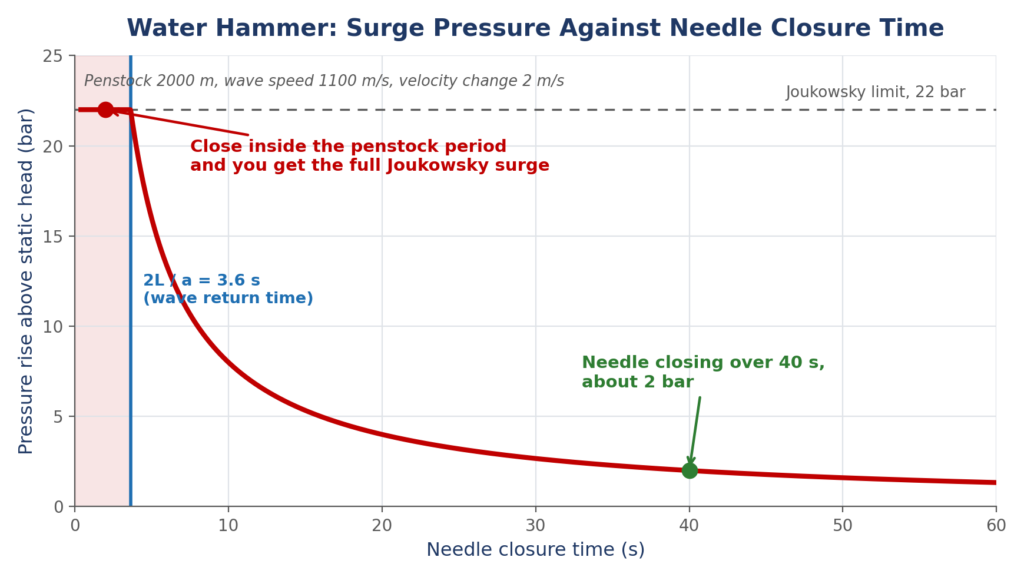
Close faster than the time a pressure wave needs to travel the penstock and return, and you get the full surge. That is why the deflector cuts the jet while the needle closes slowly.
A high head plant sits at the bottom of a long penstock, and the water inside carries enormous momentum. Stop that flow quickly and the pressure rise is density times wave speed times the change in velocity. In a steel penstock the wave travels at roughly 1000 to 1200 meters per second, so removing just 2 meters per second of flow can put 20 to 25 bar on top of the static head. Whether you get the full surge depends on the closure time against the time the wave needs to reach the reservoir and return, twice the penstock length divided by the wave speed. That is the entire reason a Pelton machine has a deflector: it cuts the jet off the runner in a second or two to control the speed rise, while the needle closes far more slowly so the water decelerates gently.
The cost. A pressure surge that can burst the penstock, shift an anchor block, or destroy the inlet valve. That is a safety event, not a maintenance one.
The fix. Run the hydraulic transient analysis for the real penstock, covering load rejection, needle closure, and deflector operation together. Set the needle closure time against the penstock period rather than a governor default, size a surge tank where the layout calls for one, and prove the sequence in analysis before it gets proved on site.
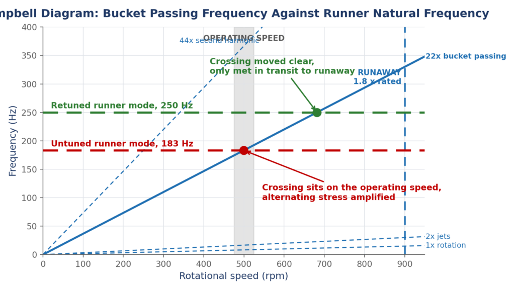
Buckets pass the jet at the bucket passing frequency. Put a runner or shaft natural frequency near it and the alternating stress from point one is multiplied.
The jet does not load the runner smoothly. Each bucket enters and leaves the jet in turn, so the excitation arrives at the bucket passing frequency, the number of buckets multiplied by rotational speed, and at its harmonics. With several jets the pattern repeats for each one. If a natural frequency of the runner, shaft, or bearing support sits near any of those excitations in the operating range, the response is amplified and the alternating stress at the bucket root rises with it. That is how a runner with a reasonable static design ends up cracking on schedule.
The cost. Amplified alternating stress that turns a sound fatigue design into a cracked one, plus bearing wear, seal wear, and noise.
The fix. Run a modal analysis of the runner and rotating assembly, including the added mass of the surrounding water, which shifts the frequencies noticeably. Build a Campbell diagram with the bucket passing frequency and its harmonics across the full speed range including runaway, keep natural frequencies clear of the crossings, and stiffen or retune where a crossing cannot be avoided.
A Pelton wheel is sold as a hydraulic machine and it fails as a mechanical one. The bucket does not break because the velocity triangle was wrong. It breaks because it was loaded a few hundred million times, or the river sanded the splitter until it stopped splitting, or it was spun to runaway by an event the structural model never saw. The efficiency curve tells you what the machine does on the day it is commissioned. It does not tell you what will be left after a decade of cycles, sediment, and transients.
At Developmech, we do the structural and flow engineering behind hydro equipment: bucket and runner fatigue FEA, erosion prediction with particle tracking CFD, runaway and overspeed load cases, penstock transient analysis, and rotordynamics with Campbell diagrams. If you build or operate high head hydro that has to survive sand, cycles, and transients, we are glad to take a look.
