Address
Malik Saleem Plaza, New City, Wah
Pakistan
WhatsApp: +92 327 5100047
Email: info@developmech.com
Work Hours
Monday to Friday: 3PM - 11AM
Weekend: 10AM - 5PM
Address
Malik Saleem Plaza, New City, Wah
Pakistan
WhatsApp: +92 327 5100047
Email: info@developmech.com
Work Hours
Monday to Friday: 3PM - 11AM
Weekend: 10AM - 5PM

Why a part that passes static FEA still cracks, seizes, or loosens after a few hundred hours of running
Developmech | Engineering Analysis & Powertrain
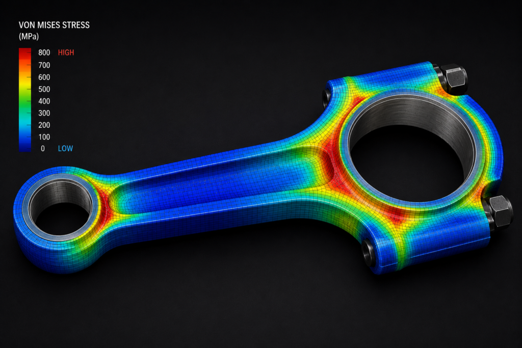
An engine is the most hostile environment most mechanical parts will ever see. High cyclic loads, steep thermal gradients, combustion pressure spikes, vibration, and clearances measured in microns all at once, for thousands of hours.
Which is why the static FEA that clears a bracket tells you almost nothing about a connecting rod. A part can pass every static strength check you throw at it and still crack, seize, or work loose in service not because the analysis was done badly, but because it answered the wrong question.
Here are the six mistakes that most often turn a component that looked fine in CAD into a warranty claim and what each one really costs.
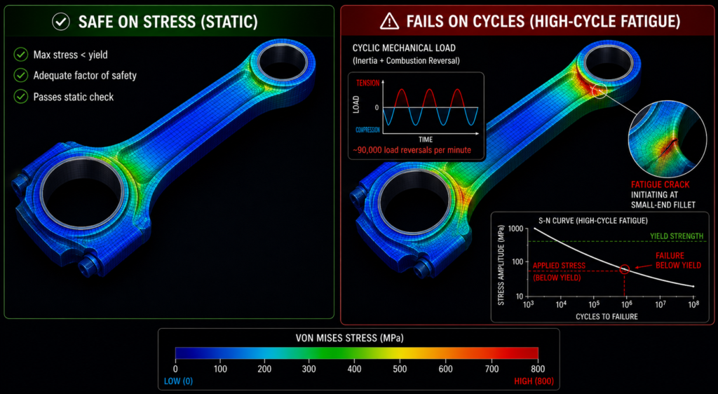
A part can sit comfortably below yield and still fail fatigue cracks initiate at stresses a static check calls safe.
A connecting rod at 3,000 rpm sees roughly 90,000 load reversals every minute. Over a service life, that’s hundreds of millions of cycles. Engine components live deep in the high-cycle fatigue regime, where failure happens at stress levels a static analysis reports as perfectly safe. Checking peak stress against yield answers a question the engine never asks.
The cost. Cracked rods, broken valve springs, failed crankshafts failures that don’t just fail the part, they destroy the engine around it. This is recall territory, not rework territory.
The fix. Run fatigue analysis, not just strength analysis. Use real load spectra, S-N or strain-life data for the actual material and surface finish, and check mean-stress effects. Design against endurance limits, and treat surface finish, fillets, and residual stress as the design variables they are.
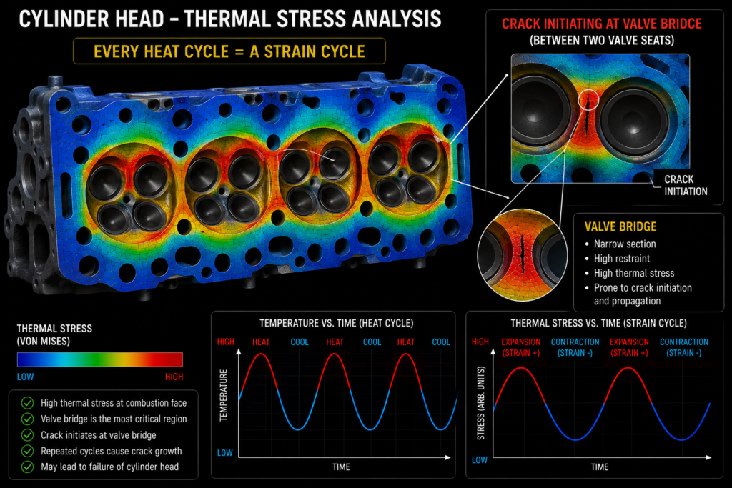
Every heat-up and cool-down cycle drives a strain cycle cracks grow at the hottest, most constrained features.
Cylinder heads, pistons, exhaust manifolds, and turbo housings don’t just run hot they run hot, then cold, then hot again. Constrained thermal expansion turns every start-stop cycle into a strain cycle. Add creep at temperature and you get thermal-mechanical fatigue: the dominant failure mode in hot engine components, and one a room-temperature stress plot cannot see.
The cost. Cracked heads and manifolds typically discovered in durability testing, months into a program, when a redesign means re-tooling a casting.
The fix. Model the thermal transient, not just the steady state. Couple the thermal and structural analyses, use temperature-dependent material properties, and evaluate TMF at the hot, constrained features (valve bridges, port junctions, thick-to-thin transitions) where the cracks actually start.
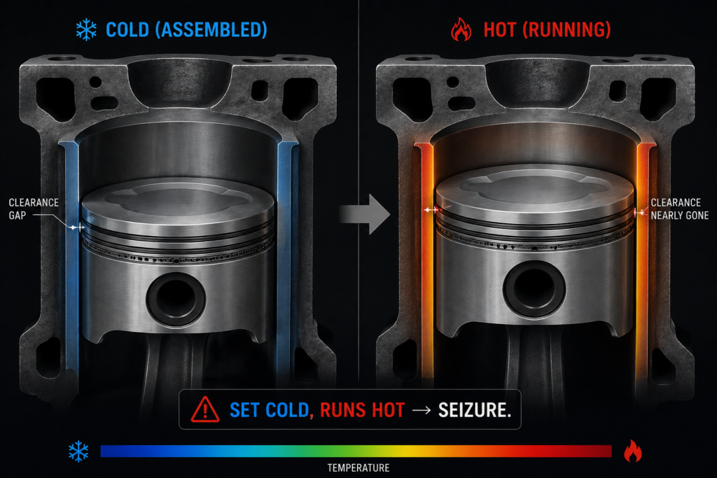
Clearances set at assembly temperature disappear as the part heats and grows too little and it seizes, too much and it knocks.
Parts are assembled cold and run hot, and they don’t all grow at the same rate. An aluminum piston in an iron bore expands roughly twice as fast as its housing. Set the clearance for the cold, assembled state and you can end up with a piston that seizes at operating temperature or, having over-corrected, one that slaps and wears when cold.
The cost. Scuffing, seizure, bore scoring, excessive oil consumption, and noise all of it discovered on a running engine, not on a screen.
The fix. Analyze clearances hot, not cold. Model differential thermal expansion between mating parts and materials, and design the cold clearance so that the running clearance lands where it needs to be across the full operating range not just at one convenient temperature.
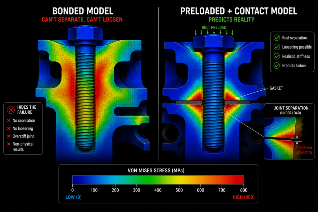
A bonded joint can never separate; a real preloaded joint can and that’s exactly where bolts fatigue and gaskets leak.
Head bolts, main-bearing caps, and con-rod bolts are among the most highly-loaded fasteners in the machine, and they’re routinely modeled as if the parts were glued together. A bonded joint cannot separate, cannot slip, and cannot lose preload so the model hides the exact behaviors that make bolted joints fail.
The cost. Fatigued bolts, blown gaskets, fretted joint faces, and loosening under vibration failures that a bonded model is structurally incapable of predicting.
The fix. Model preload and contact explicitly. Apply real bolt preload, use contact at the joint faces, include gasket stiffness, and check joint separation and bolt stress amplitude under the full cyclic combustion load not just the peak.
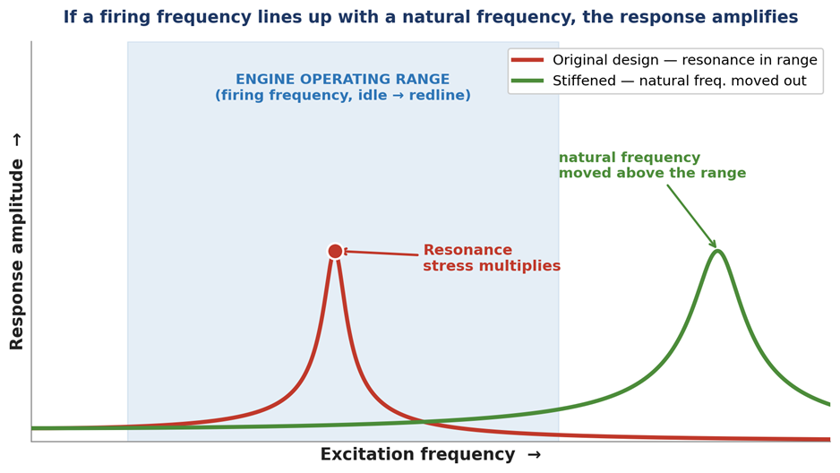
If a forcing frequency lines up with a natural frequency, the response amplifies no static load case will ever show it.
An engine is a vibration machine. Firing pulses, reciprocating inertia, and torsional excitation all sweep across a wide frequency range as the engine changes speed. If any of that lines up with a component’s natural frequency, the response amplifies dramatically and a part that’s comfortably strong under its static load can be shaken apart.
The cost. Cracked brackets, failed valve springs and covers, broken exhaust hangers, torsional damage to the crank and NVH complaints that are expensive to chase after launch.
The fix. Run modal analysis early and check natural frequencies against the engine’s operating range and firing orders. Where they collide, move the frequency (stiffen, add ribs, change mounting) or add damping and follow up with harmonic or transient dynamic analysis where the stakes justify it.
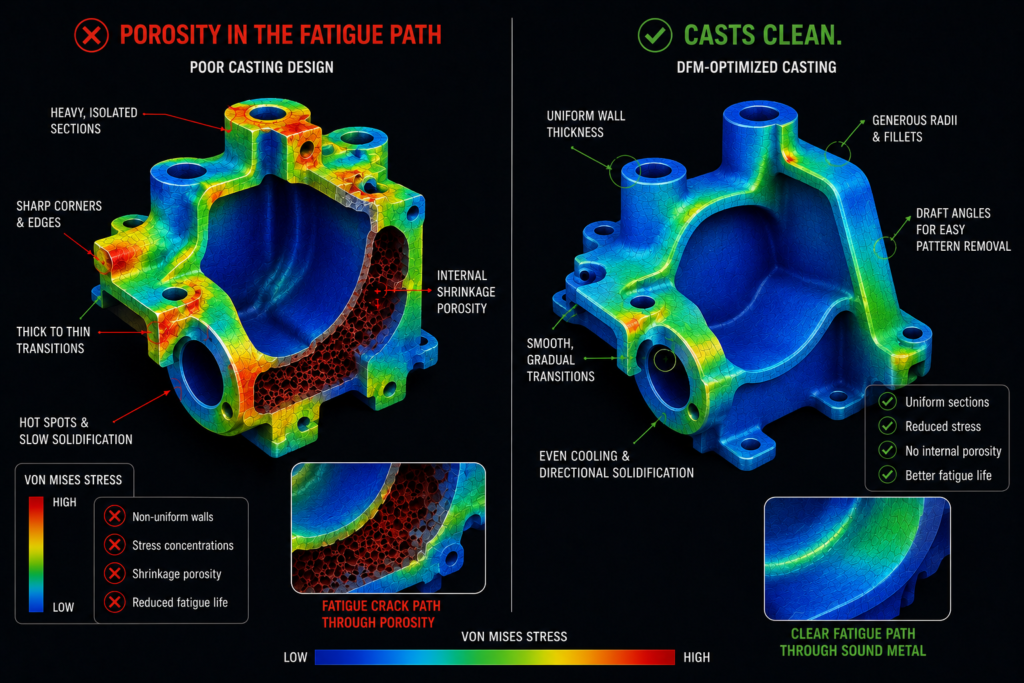
Heavy sections and abrupt transitions trap porosity (left); uniform walls and generous radii cast clean (right).
Most engine components are castings, and castings punish the same design habits injection molding does: non-uniform wall thickness, heavy isolated sections, sharp internal corners, no draft, and cores that can’t be supported or removed. Worse, the resulting shrinkage porosity lands inside the part invisible, and squarely in the path of the fatigue loading from mistake #1.
The cost. Low casting yield, scrapped parts, and porosity-initiated fatigue cracks in parts that passed every inspection they were given.
The fix. Design for the process. Keep walls uniform, add generous fillets, provide draft, ensure the casting can feed and solidify progressively, and make sure machining datums and access are planned. Run casting simulation where the part is critical finding a hot spot on a screen costs nothing; finding it in a rod is a recall.
Every one of these is the same failure of imagination: analyzing the part in a state the engine never actually puts it in. Cold instead of hot. Static instead of cyclic. Bonded instead of bolted. Steady instead of shaking. The component isn’t failing because the math was wrong it’s failing because the math was asked the wrong question. Engine components are unforgiving precisely because they punish every simplification you make.
At Developmech, we analyze engine and powertrain components the way they actually run hot, cyclic, preloaded, and vibrating with fatigue, thermal, and dynamic analysis backed by manufacturable design. If you’ve got a component that has to survive real duty cycles, we’re glad to take a look.
