Address
Malik Saleem Plaza, New City, Wah
Pakistan
WhatsApp: +92 327 510047
Email: info@developmech.com
Work Hours
Monday to Friday: 3PM - 11AM
Weekend: 10AM - 5PM
Address
Malik Saleem Plaza, New City, Wah
Pakistan
WhatsApp: +92 327 510047
Email: info@developmech.com
Work Hours
Monday to Friday: 3PM - 11AM
Weekend: 10AM - 5PM
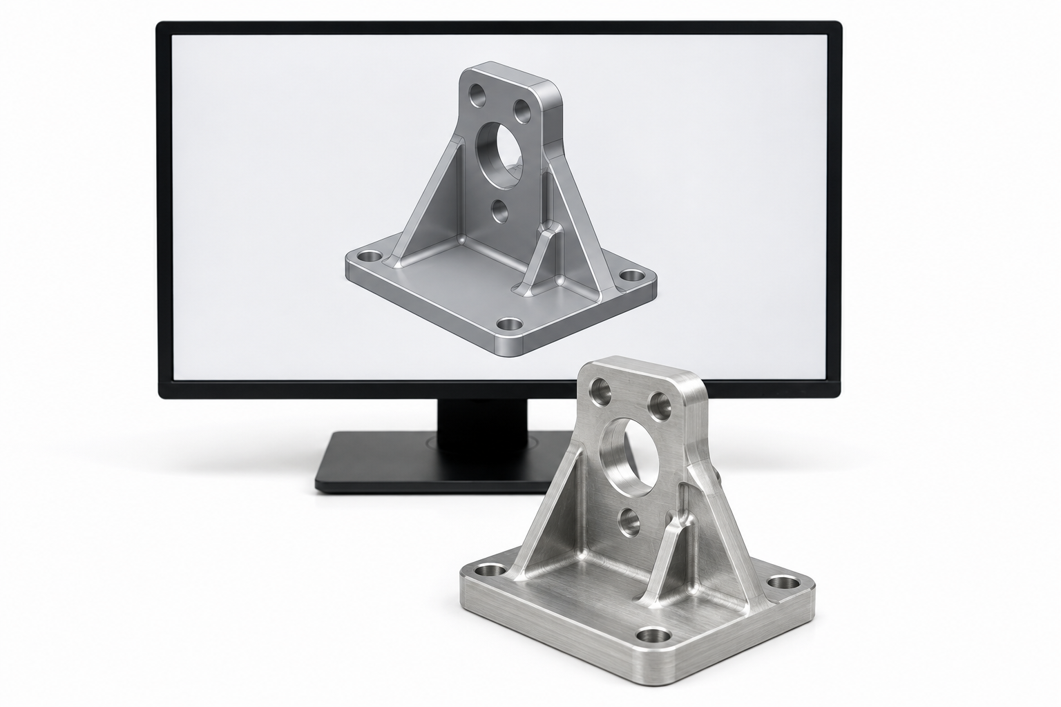
A 3D model is nominal, perfectly rigid, and defect free, and the real part is none of those, so every idealization in the model is a place the part bites back
Developmech | Design, Simulation & Tolerance Analysis
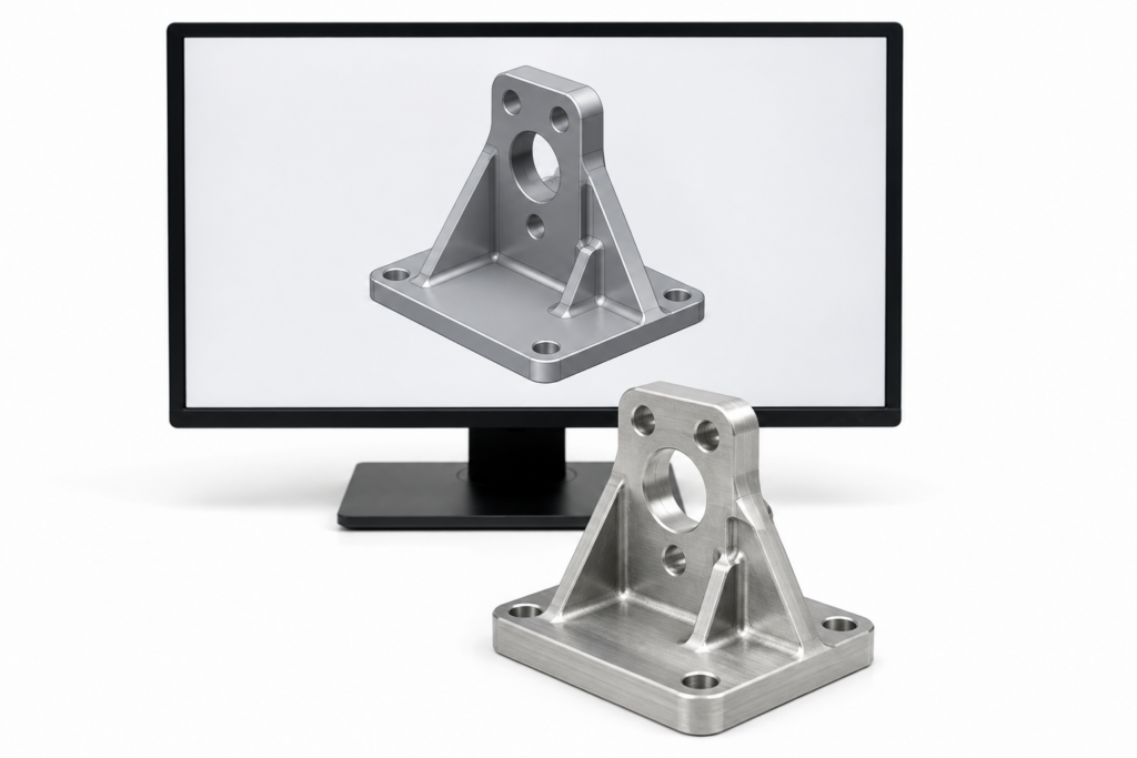
A 3D model is a beautiful lie. On the screen the part is perfect: every dimension exact, every corner as sharp or round as you drew it, the whole thing infinitely rigid, weightless until you ask for a mass, and without flaw. It assembles with its neighbors to the micron, never sags, and is made of a material with no scatter. None of that is true of the part that gets made, and the gap between the perfect model and the imperfect part is where a surprising amount of engineering trouble lives.
The model is not wrong, it is idealized, and every idealization is an assumption reality is allowed to break. The dimensions are really distributions that stack up, the rigid body deflects, the nominal mass sits somewhere different, the geometry may not be something a machine can cut, the assembly that mates on screen may not go together on the bench, and the pretty geometry is not what you hand a solver. A model is a statement of intent, not a description of the part.
Here are the six ways the perfect model and the real part disagree, and why the difference is an engineering problem, not a drafting one.
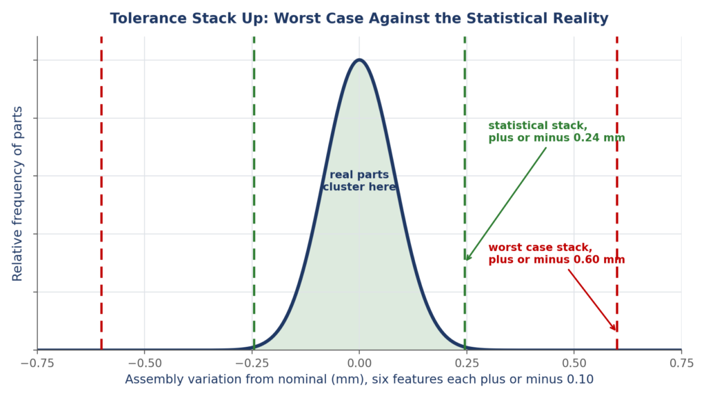
No dimension is exact, each has a tolerance, and in an assembly those tolerances stack. Add them worst case and the gap is huge, combine them statistically and it is tighter, but the stack is always there.
The model shows every dimension as one exact number, but no part is ever made to one, each comes out somewhere inside a tolerance band. On a single feature that is easy to forget, but in an assembly the tolerances stack, and the fit at the end of a chain of parts is the sum of all of them. Add them worst case and the stack can be far larger than any single tolerance suggests, so a fit that looks fine on the nominal model can bind or fall apart once real parts are combined. Tolerances are the difference between a model that assembles and a batch that sometimes does not.
The cost. Assemblies that bind, rattle, or will not go together at the tolerance extremes, from a stack that was never added up, on parts that each measured perfectly.
The fix. Analyze the stack, do not trust the nominal. Build the tolerance chain for every critical fit, add it worst case where failure is unacceptable and statistically where a small reject rate is allowed, put the tolerance where it is cheap and the precision where it is needed, and design the fit to survive the whole stack.
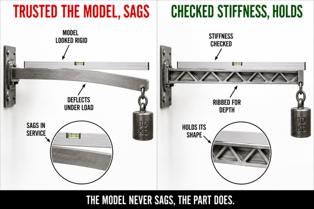
A solid model never sags. The real part deflects under load and under its own weight, so a shape that looks fine on screen can droop, bind, or lose its tolerance the moment it is real.
A part in a model is infinitely stiff, but a real part deflects. Under its working load, and often under nothing more than its own weight, it bends and sags by amounts the model never shows, and for anything long, thin, or lightly supported that deflection can dwarf the tolerances you agonized over. A shaft that is straight on screen droops between its bearings, a bracket flexes under its load, a long cover bows under gravity, and the clearances that were perfect quietly disappear. The model shows the shape, not what the shape does under load.
The cost. Parts that sag, flex, and lose their clearances under load or their own weight, in ways the rigid model never revealed, spoiling fits that were perfect on screen.
The fix. Check the stiffness, not just the shape. Calculate or simulate the deflection under the real loads and gravity, design the section and supports for the deflection the function can tolerate, and remember that stiffness, not strength, usually governs whether a part holds its shape.
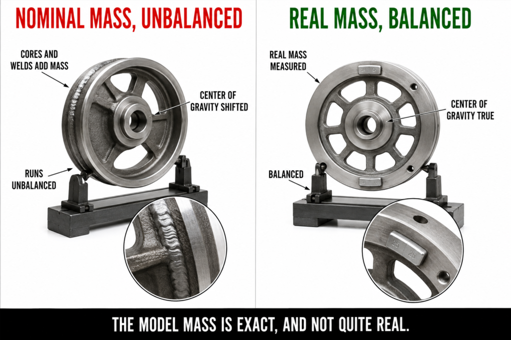
The model gives a clean center of gravity and inertia from nominal geometry and one density. Cores, welds, tolerances, and process move the real mass, so a balance or a handling calculation done on the nominal can be off.
Ask a model for the mass, the center of gravity, and the inertia, and it answers instantly, from perfect geometry and a single density. The real part carries its mass somewhere slightly different, because cores shift, wall thicknesses vary, welds add metal, and the density is not the handbook value. For most parts that does not matter, but where it does, a rotor that must be balanced, a mechanism whose center of gravity sets how it tips, a payload whose inertia drives its control, the gap becomes a real problem. The model gives the mass of the drawing, not of the part.
The cost. Rotating parts that vibrate because the real center of gravity is off the model’s, and mechanisms and payloads that behave differently from the nominal mass they assumed.
The fix. Design for the real mass, not the nominal. Allow for the tolerances, cores, and welds when the balance or inertia matters, add balancing or trimming features where a part must run true, and verify the mass properties on real parts rather than trusting the model’s clean number.
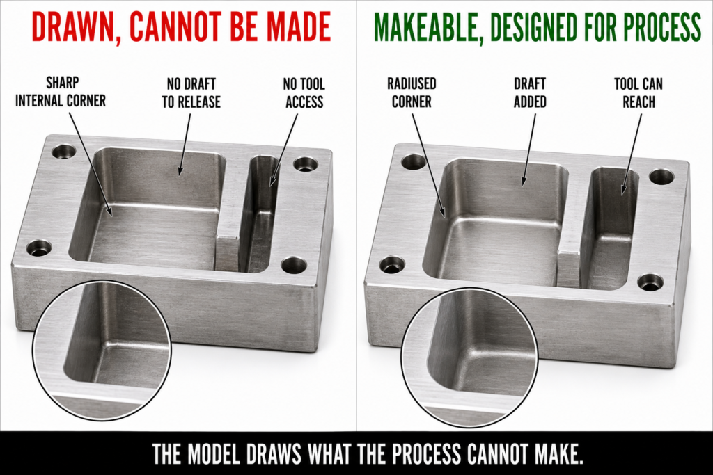
A model will happily show a perfectly sharp internal corner, a pocket no tool can reach, or a molded wall with no draft. The modeler does not care whether it can be made. The machine does.
A modeler will let you draw anything: a perfectly sharp internal corner no cutter can produce, a deep narrow pocket no tool can reach the bottom of, a molded wall with no draft that will never leave its tool. The geometry is valid in the model and impossible on the machine, and the gap only shows up when someone tries to make it, usually late and expensively. A 3D model is a description of a shape, not a promise that it can be manufactured, and the manufacturability has to be designed in, not assumed because the model built without complaint.
The cost. Geometry that cannot be machined, cast, or molded as drawn, found in the shop rather than the model, forcing redesign, rework, or costly tooling late.
The fix. Model for the process, not just the shape. Put radii on internal corners for the cutter, add draft to cast and molded faces, keep pockets within reach of real tools, provide access to clean and inspect internal features, and check every part against how it will actually be made before release.
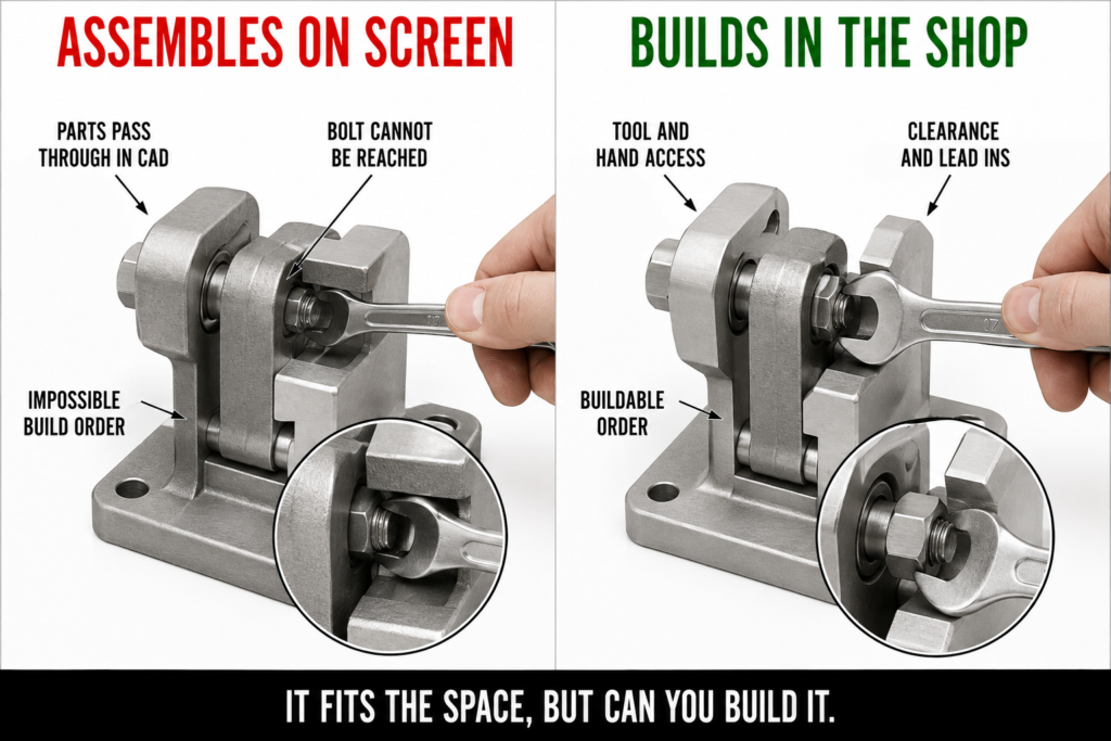
A model can mate parts that interfere, bolt joints no wrench can reach, and assemblies that cannot physically go together in any order. Assembling on screen is not the same as assembling on the bench.
An assembly in a model goes together perfectly, because the software lets parts pass through one another, mate to interfering faces, and ignore whether there is any physical way to put them together. On the bench, the same assembly may have parts that interfere, fasteners with no room for a wrench, components that cannot be fitted in any order because each blocks the next, and clearances that vanish once tolerances are real. The model checks that the parts can coexist in space, not that anyone can assemble them. A model that assembles is a start, not a proof that the product can be built.
The cost. Interfering parts, fasteners that cannot be reached, and assemblies that go together in no order, all found on the first real build, not in the model that mated cleanly.
The fix. Design the assembly, not just the parts. Check interferences and clearances with real tolerances, provide tool and hand access to every fastener, work out and validate the assembly sequence, and confirm the product can be put together and taken apart, not just that the parts fit in space.
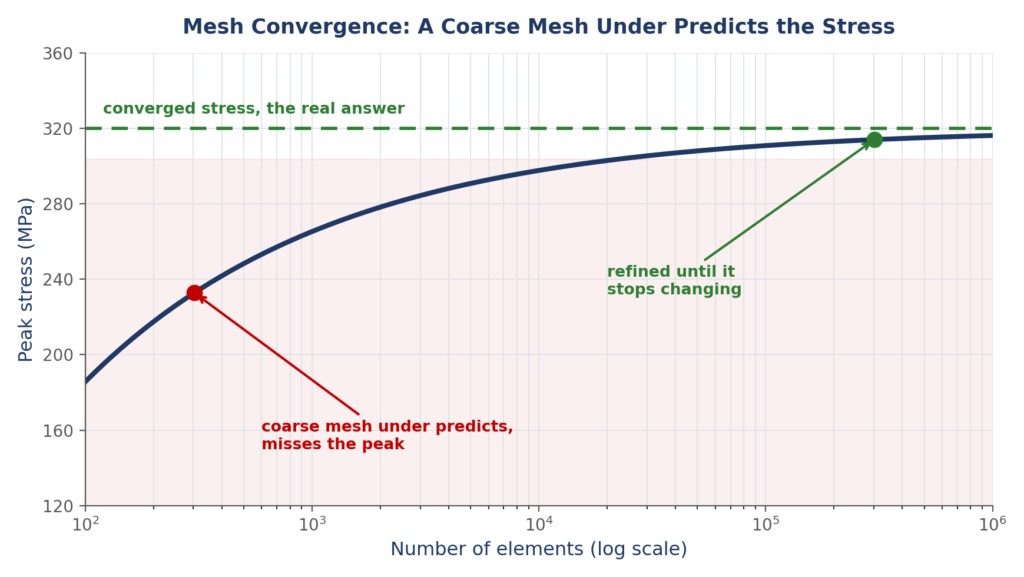
The detailed CAD geometry is not what you hand a solver. It has to be simplified, meshed, and given loads and supports, and a coarse mesh or a wrong boundary condition gives a confident, wrong answer.
The fully detailed CAD model is not the model you should analyze, and treating it as one is how simulations mislead. To be solved it has to be simplified, meshed into elements, and given loads and supports, and every one of those steps changes the answer. A mesh too coarse to catch a stress concentration reports a stress far below the real one, a wrong boundary condition shifts the whole result, and a defeatured fillet hides the very spot the part will crack. The danger is that the solver always returns a clean, confident number, whether or not the model behind it was right. The pretty geometry is the start of the analysis, not the analysis.
The cost. Confident, wrong simulation results from a mesh too coarse, a feature defeatured away, or a boundary condition that does not match reality, trusted for the clean number.
The fix. Build the analysis model deliberately. Simplify with judgment but keep the features that drive the result, refine the mesh until the answer stops changing, set boundary conditions that match how the part is really loaded and held, and check the simulation against hand calculations or tests, not the first clean number.
A 3D model is a statement of what you want, made of perfect geometry, infinite stiffness, nominal mass, and no defects, and the real part is a negotiation with tolerance, deflection, mass, manufacturing, assembly, and the physics a solver only approximates. The part does not fit the way the nominal said, it deflects where the model was rigid, its mass sits where the model did not put it, it may not be makeable or assemblable as drawn, and its simulated behavior is only as good as the analysis model behind the pretty one. None of these is a drafting error, they are engineering decisions the model hides until a real part exposes them. Treat the model as the beginning of the engineering, tolerance it, check its stiffness and mass, design it to be made and assembled, and analyze it honestly, and it becomes a part that works. Treat the perfect picture as the finished job, and reality hands back the difference.
At Developmech, we do the engineering between the model and the part: tolerance stack up and fit, deflection and stiffness, mass properties and balance, design for manufacture and assembly, and simulation models built and checked to give answers you can trust. If you turn 3D models into parts that have to fit, hold, and work, we are glad to take a look.
