Address
Malik Saleem Plaza, New City, Wah
Pakistan
WhatsApp: +92 327 5100047
Email: info@developmech.com
Work Hours
Monday to Friday: 3PM - 11AM
Weekend: 10AM - 5PM
Address
Malik Saleem Plaza, New City, Wah
Pakistan
WhatsApp: +92 327 5100047
Email: info@developmech.com
Work Hours
Monday to Friday: 3PM - 11AM
Weekend: 10AM - 5PM

An injection molded part shrinks, warps, sinks, and knits as the plastic flows and cools, so the mold has to be cut for what the plastic does, not for the part you drew
Developmech | Flow, Thermal & Tooling Analysis

An injection molded part looks like it should be easy to predict. You draw the part, cut a cavity that is its exact negative, inject molten plastic, and out comes a copy of the cavity. Except it does not. Plastic shrinks a great deal as it cools, flows in ways that leave marks, and pulls itself out of shape as it freezes. The part that comes out of the mold is never quite the shape of the cavity, and the mold has to be designed for that difference.
The reason is that molding is a flow and cooling process, not a copying one. Hot plastic is packed into a cold cavity, and as it cools from the outside in it shrinks unevenly, warps toward its thicker regions, sinks where the walls are thick, leaves a weak line wherever two flow fronts meet, and has to be forced out of a cavity it is gripping. None of that is on the part drawing, and all of it is designed into the mold, which is why the cavity is never simply the shape of the part.
Here are the six ways the molded part departs from the cavity, and why not one of them is a crack.
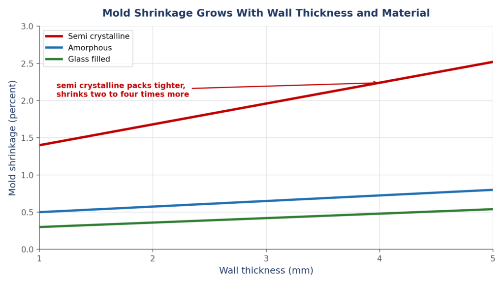
Plastic shrinks as it cools, by a percent or several, so the cavity is cut oversize by the shrink factor. The shrinkage grows with wall thickness and is far larger for semi crystalline plastics than amorphous ones.
The most basic fact of molding is that plastic shrinks as it cools, and not by a little. A part can come out a full one or two percent smaller than the cavity that made it, so the cavity is cut deliberately oversize by the expected shrinkage. That number is not constant: it grows with wall thickness, because thicker walls hold more heat, and it is far larger for semi crystalline plastics, which pack tighter as they solidify, than for amorphous ones. Get the shrink factor wrong and every part comes out the wrong size, and if the shrinkage is uneven, oversizing the cavity cannot save it.
The cost. Parts that come out the wrong size because the cavity was cut to the drawing rather than oversized for shrinkage, or that vary because the shrink factor was wrong for the wall or the material.
The fix. Cut the cavity for the shrinkage. Apply the right shrink factor for the exact material and wall, keep walls uniform so the shrinkage is even, verify it on a first article and adjust the steel, and treat shrinkage as a designed in allowance.

When one part of the molding shrinks more than another, it pulls the part out of shape. Thick and thin sections, uneven cooling, and fiber orientation all warp the part as it freezes.
Shrinkage would be easy to handle if it were uniform, but it never is. Different regions cool and shrink at different rates: a thick section shrinks more than a thin one beside it, a hard cooled face less than a slowly cooled one, and in a filled plastic the fibers shrink differently along and across the flow. Each makes one region pull harder than its neighbor as the part freezes, and the part bows, twists, or dishes toward wherever it shrank most. This is warpage, the difference between a part that comes out flat and true and one that comes out visibly bent, driven not by any load but by uneven cooling and shrinkage.
The cost. Parts that bow, twist, or dish as they cool because one region shrank more than another, coming out of the mold visibly bent with no load ever applied.
The fix. Balance the shrinkage. Keep the walls uniform, cool the mold evenly so no region freezes far ahead of another, gate so the fill and packing are even, and predict the warpage from the cooling and flow so it is designed out, not found on the first shots.

A thick section cools slowly from the outside in, and as the inside shrinks last it either pulls the surface in as a sink mark or tears open into an internal void. Thick is the enemy.
Plastic cools from the surface inward, so the outside of a thick section freezes first and the core last, and when that trapped core finally shrinks it has to pull material from somewhere. Pull the still soft surface inward and you get a sink mark, a dimple over the thick spot, and if the surface has already frozen, the shrinking core tears open inside instead, leaving a void. Both come from a section too thick to cool evenly, and they cluster exactly where designers add material for strength, behind bosses, ribs, and thick junctions. In molding, thick is not strong, it is slow, sunken, and hollow.
The cost. Sink marks dimpling the surface over thick features, and hidden internal voids where thick cores shrank away, right at the bosses and ribs added for strength.
The fix. Core out the thick. Keep walls thin and uniform, hollow out heavy sections and thick bosses, blend ribs into walls at a fraction of the wall thickness, and add strength with ribs and shape, not solid thickness the mold cannot cool.

When the melt splits around a hole or meets from two gates, the fronts rejoin as a weld line that is cosmetically visible and structurally weak, because the plastic never fully knits back together.
Molten plastic fills a cavity as advancing fronts, and wherever a front splits and rejoins, around a hole, a pin, or a boss, or where two gates meet, the fronts weld back together as a line. The trouble is that they do not fully knit: the plastic there is cooler, the molecules do not tangle across the join, and often air is trapped, so a weld line is both visible and weaker than the material around it. A part can look filled and complete and still be weak exactly along the line where its flow fronts met, and that line sits wherever the geometry and the gates put it.
The cost. Weld lines that show as a visible mark and run as a plane of weakness, sitting behind every hole and boss and wherever two flow fronts meet, weaker than the plastic around them.
The fix. Put the weld lines where they can live. Position gates so the fronts meet away from the highest stress and visible faces, keep the melt hot enough to knit, and check the fill to see where the weld lines land before the mold is cut.

A molded part shrinks onto the cores and grips them, so every face must be tapered with draft to release. Too little draft and the part drags, scuffs, sticks, or is pushed out of shape by the ejectors.
A molded part shrinks tightly onto the cores as it cools and grips them hard, so it has to be pushed off by ejector pins when the mold opens. For that to work, every face that runs in the direction the mold opens must be tapered slightly, given draft, so it can break free and slide out. A wall drawn perfectly straight, with no draft, drags against the steel, scuffs, and sticks, and the ejectors dent it forcing it out, or it will not release at all. Undercuts make it worse, a feature that hooks behind the steel needs extra moving parts. Draft is not optional detailing, it is what lets the part exist as a separate object.
The cost. Parts that stick, scuff, and drag on straight walls, ejector pins that dent and distort them, and undercuts that cannot release without extra mechanism in the mold.
The fix. Draft every face and design for release. Put draft on all faces along the pull, more on textured surfaces, avoid undercuts or plan the side actions they need, and check every feature can come out of the steel before the mold is built.

Plastic can only flow so far through a thin section before it freezes, and the pressure to fill climbs steeply with flow length. Gate in the wrong place and the part short shots, flashes, or packs unevenly.
Where the plastic enters, the gate, decides how the whole part fills. Molten plastic freezes as it flows, so it can only travel so far through a given wall before it stalls, and the pressure to push it climbs steeply the farther it goes. Gate so the flow reaches too far and the corners never fill, a short shot, force it harder and the mold flashes at the parting line, and even when it fills, regions near and far from the gate pack under different pressures and shrink differently, feeding back into warpage. The gate and its flow are the first thing that decides whether the part is even makeable.
The cost. Short shots where the flow could not reach, flash where it was forced too hard, and uneven packing and warpage from regions filled at different pressures, all set by the gate.
The fix. Gate for the flow. Place the gate so the flow length stays within what the wall can fill, balance the runners so every region fills together, keep walls thick enough to flow and thin enough to cool, and simulate the fill before the steel is cut.
An injection molded part is not a copy of the cavity, it is what the plastic becomes as it flows in and cools, and everything about it comes from that flow and cooling, not from the drawing. It shrinks so much the cavity is cut oversize, warps where the shrinkage is uneven, sinks and voids where the walls are thick, forms a weak line wherever two flows meet, grips the cores so hard it needs draft and ejectors to escape, and fills only if the gate and flow are right. Not one of those six is a crack, they are shrinkage, warpage, sink, a weld line, release, and flow, and every one is designed into the mold or fought on the shop floor. Design the part and mold for how the plastic actually flows and cools, keep the walls thin and even, draft every face, and put the gates and weld lines where they belong, and the molding comes out right. Draw the cavity as the exact shape of the part, and the plastic will make something else.
At Developmech, we do the engineering behind molded parts and their tools: shrinkage and warpage, wall thickness and sink, weld lines and flow, draft and ejection, and the gate, runner, and cooling design that fill a part cleanly. If you are taking a plastic part to a mold, we are glad to take a look.
