Address
Malik Saleem Plaza, New City, Wah
Pakistan
WhatsApp: +92 327 510047
Email: info@developmech.com
Work Hours
Monday to Friday: 3PM - 11AM
Weekend: 10AM - 5PM
Address
Malik Saleem Plaza, New City, Wah
Pakistan
WhatsApp: +92 327 510047
Email: info@developmech.com
Work Hours
Monday to Friday: 3PM - 11AM
Weekend: 10AM - 5PM

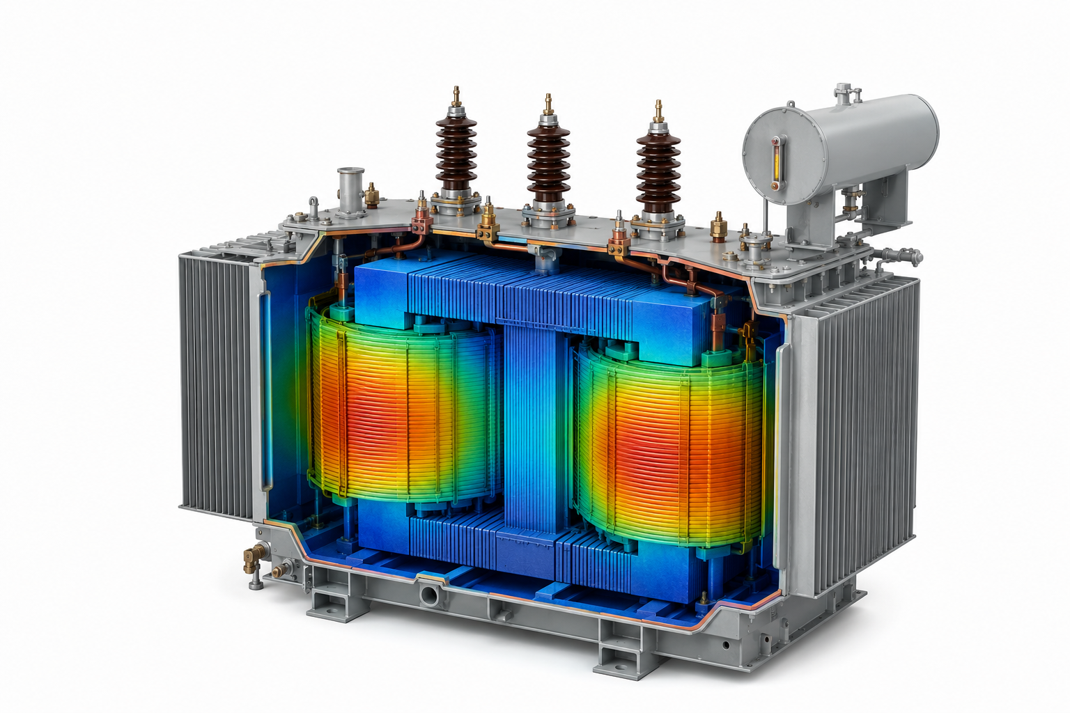
Heat, short circuit forces, and vibration decide whether a transformer lasts thirty years or trips out in three, and none of it is on the electrical datasheet
Developmech | Thermal, Structural & Vibration Analysis
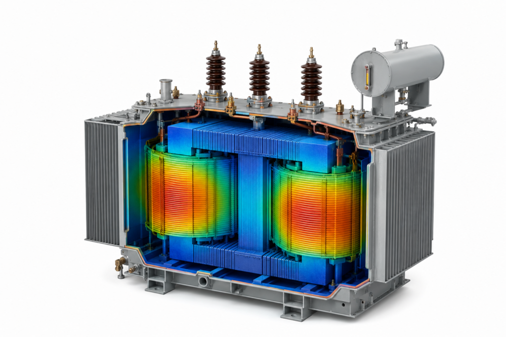
Ask what a transformer is and you get an electrical answer: two coils, a magnetic core, a turns ratio. Ask why transformers fail and the answer is almost never electrical. They overheat. Their windings are torn apart by fault forces. They vibrate themselves loose. They leak, rupture, and crack. A transformer is an electrical machine that dies for mechanical and thermal reasons.
That gap matters, because the electrical design can be flawless and the transformer will still fail if the heat has nowhere to go, the windings cannot survive a fault, or the structure resonates with its own hum. The datasheet covers the volts and the amps. It says almost nothing about the engineering that actually keeps the thing alive.
Here are the six mechanical and thermal reasons transformers fail, and what each one costs.
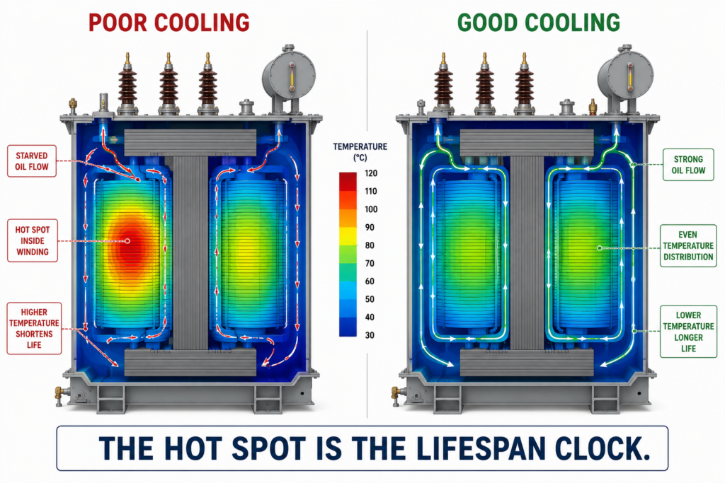
Insulation ages by temperature. Every 7 to 8 degrees C of extra hot spot roughly halves its life, so cooling is not a detail, it is the design.
A transformer’s life is really the life of its insulation, and insulation ages chemically at a rate that doubles for roughly every 7 to 8 degrees C of temperature rise. That makes the winding hot spot, not the average temperature, the number that decides how long the transformer lasts. Undersized radiators, poor oil or air flow, a hot spot the cooling never reaches, and the transformer that tested fine is quietly cooking its own insulation.
The cost. Insulation that ages years faster than rated, thermal faults, and in the worst case a runaway where a hot spot degrades the oil and the insulation together. The failure looks electrical. The cause was a cooling path that was never analyzed.
The fix. Treat cooling as a core part of the design. Use CFD to map oil and air flow and find the real hot spots, size radiators and fans to the actual duty and ambient, and model the winding thermal path rather than trusting a nameplate rise. A few degrees at the hot spot is worth years of life.
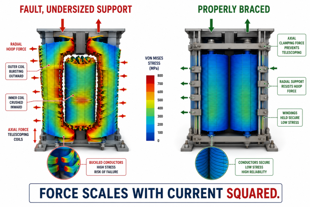
Short circuit current can hit many times rated, and force scales with current squared. The windings see tonnes of radial and axial force in milliseconds.
When a short circuit or through fault hits, the current can rise to many times the rated value, and the electromagnetic force between conductors scales with the square of that current. A fault current ten times rated is a hundred times the force. In milliseconds the windings see tens or hundreds of tonnes of load: radial hoop force trying to burst the outer winding and crush the inner one, and axial force trying to telescope the coils apart. If the winding support and the axial clamping are not designed for it, the windings buckle, shift, or loosen.
The cost. Deformed or displaced windings, and the especially dangerous case where a transformer survives a fault electrically but is mechanically damaged, so it fails on the next one with no warning.
The fix. Analyze the short circuit forces structurally, not just the currents. Run FEA on the windings and the clamping structure for the peak fault force, design the radial support and axial preload to hold the coils solid, and verify the clamping keeps its load over life.
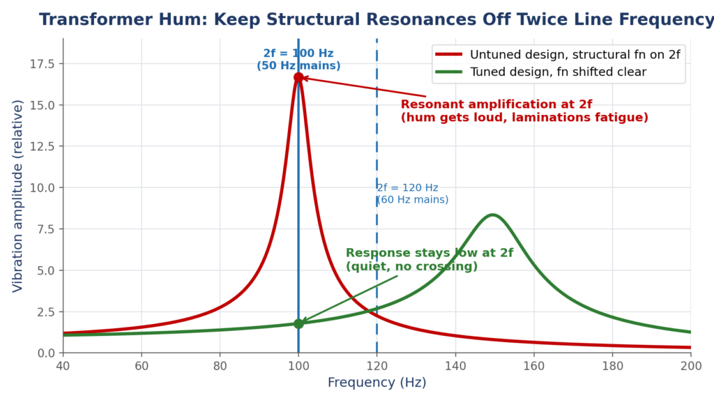
The core changes shape with the field and vibrates at twice the line frequency. If the tank or clamps resonate near it, you get noise, loosening, and fatigue.
The steady hum of a transformer is not electrical noise, it is the core physically changing dimension as the magnetic field cycles, a phenomenon called magnetostriction. The core vibrates at twice the line frequency, 100 Hz on a 50 Hz supply or 120 Hz on 60 Hz, and it drives the whole structure. If the tank walls, the core clamps, or the mounting have a natural frequency near that, the vibration amplifies, and a low hum becomes noise, loosening, and fatigue.
The cost. Noise that breaches limits and draws complaints, fasteners and clamps that work loose, fatigue cracks in the tank and brackets, and oil leaks at cracked welds and loosened joints.
The fix. Run modal analysis on the tank, core frame, and mounting, and keep their natural frequencies clear of twice the line frequency and its harmonics. Where a crossing is unavoidable, stiffen, add damping, or change the mounting, and design clamps that stay tight under the constant vibration.
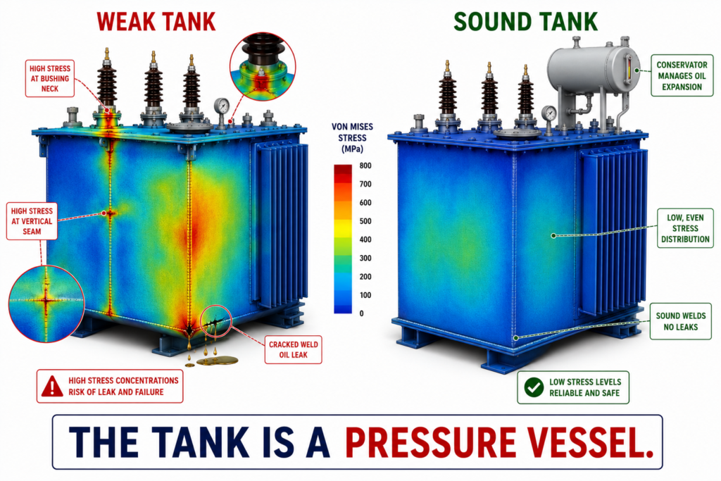
Oil expands with heat, faults can spike the pressure, and every weld and radiator is a leak path. The tank is a pressure vessel that has to breathe.
An oil filled tank is not a simple enclosure. The oil expands by several percent across the operating temperature range, so the tank has to accommodate that volume without overpressure, usually through a conservator or a sealed bladder. A serious internal fault can vaporize oil and spike the internal pressure hard enough to split a poorly designed tank. And every radiator, bushing, and seam is a potential leak path whose integrity comes down to weld quality and sheet metal design.
The cost. Oil leaks that are slow and constant or sudden and dangerous, gasket failures, and in the extreme a tank rupture during a fault, which is a safety event, not a maintenance one.
The fix. Design the tank as the pressure vessel it is. Use structural FEA for operating and fault pressure, design and inspect welds for leak free service, manage oil expansion deliberately, and treat the sheet metal and radiator design as a sealing and structural problem, not just a container.
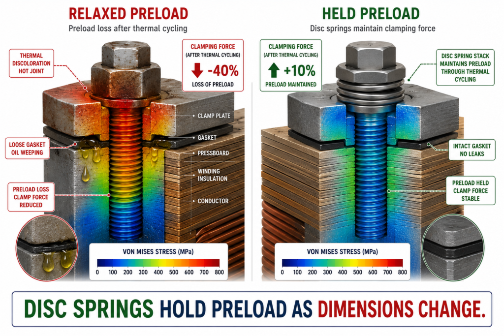
Load and ambient swings expand and contract the whole assembly. Clamping preload relaxes, gaskets take a set, and joints loosen and heat up.
A transformer never sits at one temperature. Load changes and ambient swings expand and contract the windings, the core, and the structure continually, and everything that was tight at assembly slowly stops being tight. Clamping preload relaxes, which quietly undoes the very support that protects the windings from fault forces. Gaskets take a compression set and start to weep. Bolted electrical joints loosen, and a loose joint heats up, which loosens it further.
The cost. Relaxed winding clamping that makes fault damage far more likely, oil leaks at set gaskets, and hot electrical joints that fail over time and are hard to diagnose.
The fix. Design the joints and clamping for a lifetime of thermal cycling, not for assembly day. Use disc spring stacks to hold clamping preload as dimensions change, select gaskets that resist compression set at temperature, and specify and check joint preload with the thermal range in mind.
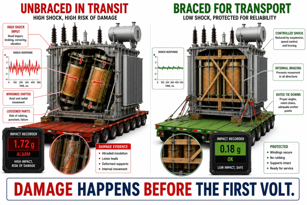
Transformers are huge and shipped far. Transport shock and lifting or seismic loads can deform windings before the unit is even switched on.
A large transformer is built in one place and used in another, and getting it there is a mechanical event in its own right. Transport shock and vibration can shift or deform windings, and lifting, jacking, and seismic loads put the tank and internal structure under loads that have nothing to do with electricity. Damage done in transit is often invisible until the unit is energized and fails, and by then the cause is long gone.
The cost. Windings displaced or clamping loosened in transit, structural damage from lifting or an earthquake, and warranty disputes where nobody can prove when the damage happened.
The fix. Design for the journey and the site, not just the service. Analyze transport shock and vibration, fit impact recorders, design lifting and jacking points and the internal bracing for handling loads, and qualify the structure for the seismic demand where it will live.
A transformer is an electrical device wrapped around a set of mechanical and thermal problems, and it fails when those problems are ignored. The winding does not burn because of a wiring error, it burns because the heat had nowhere to go, or it was torn by a fault the structure could not hold, or it was shaken loose by the core’s own hum. The electrical datasheet tells you what the transformer does. It does not tell you whether it will survive doing it. That answer is thermal, structural, and dynamic, and it is decided long before the first volt.
At Developmech, we do the mechanical and thermal engineering behind electrical equipment: cooling and hot spot CFD, short circuit and structural FEA, vibration and resonance, and the tank, weld, and clamping design that keeps it all together. If you build power equipment that has to survive heat, faults, and years of service, we are glad to take a look.
